


INTRODUCTION
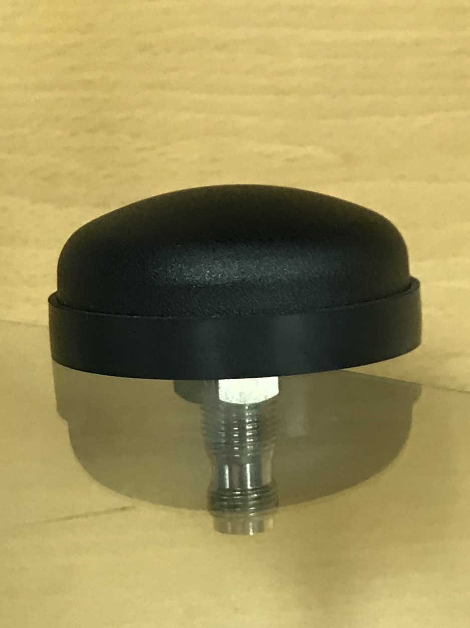
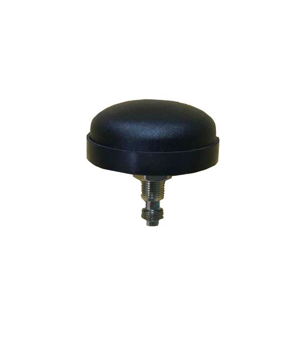
GPS/GLONASS Screws Mount Antenna CPG03-TNC female
1. GENERAL DESCRIPTION
|
Model No
|
|
CPG03-GPS/Glonass-TNC/F
|
Below is a table summarizing the
GPS(1575.42Mhz)/GLONASS(1602.00MHz) antenna design specification.
1-1. Application:
For antenna units used with or in automobile ( 50”Ė impedance ).
1-2. Appearance:
Antenna Unit
Dimensions 25.00x25.00x8.90mm
Weight 15.0Ī└1g (typ)-Without Cable & Connector
1-3. Operating Condition:
Temperature -20 to +90 Īµ
Humidity 10 to 95Żź RH
1-4. Storage Condition:
Temperature -40 to +90 Īµ
Humidity 10 to 95Żź RH
1-5. Electrical Specification:
©BAll values are defined at 25Ī└15Īµ,65 Ī└ 20ŻźRH , power handling 1 u watt ,©Bair pressure 960Ī└100 HPA unless noted.
©BPatch characteristics are measured with 70x70 mm ground plane in an anechoic chamber.
1-6) Patch
|
Characteristics
|
Specification
|
|
Center Frequency
|
1575.42(GPS)/1602.00(Glonass) Ī└1.023 MHz
(when covered with a radome and measured by LNA ground plane)
|
|
Bandwidth
(10dB return loss)
|
8 MHz min @S11©Q-10dB
|
|
Gain at Zenith
|
2.0 dBic typ
|
|
Operating Frequency
|
1568~1578Mhz(GPS)
1598~1608MHz(Glonass)
|
|
Gain at 10ĪŃelevation
|
-7 dBic min
|
|
Polarization
|
R.H.C.P
|
|
Axial Ratio
|
3 dB typ
|
|
VSWR
|
<1.5:1
|
1-7) Filter / LNA
|
Characteristics
|
Specification
|
|
Center Frequency
|
1575.42/1602.00MHz Ī└1.023 MHz
|
|
Gain
|
27~29 dB typ
|
|
Noise Figure
|
1.5 dB typ
|
|
Output V.S.W.R
|
2.0 max
|
|
Voltage
|
2.5~5.5 V
|
|
Current
|
2.5VŻ║6.6 mA Typical
|
|
|
3.0 VŻ║8.6 mA Typical
|
|
|
4.0 VŻ║12.6 mA Typical
|
|
|
5.5 VŻ║16 mA Typical
|
1-8 GPS/GLONASS Antenna Mechanical Properties
|
Parameter
|
Description
|
|
Antenna Mounting
|
Screws Mount
|
|
Waterproof
|
100 % waterproof.
|
|
Shock 10msec. Half sine wave.
|
Shock 10msec. Half sine wave.
|
|
Antenna Color
|
ABS (Black)
|
|
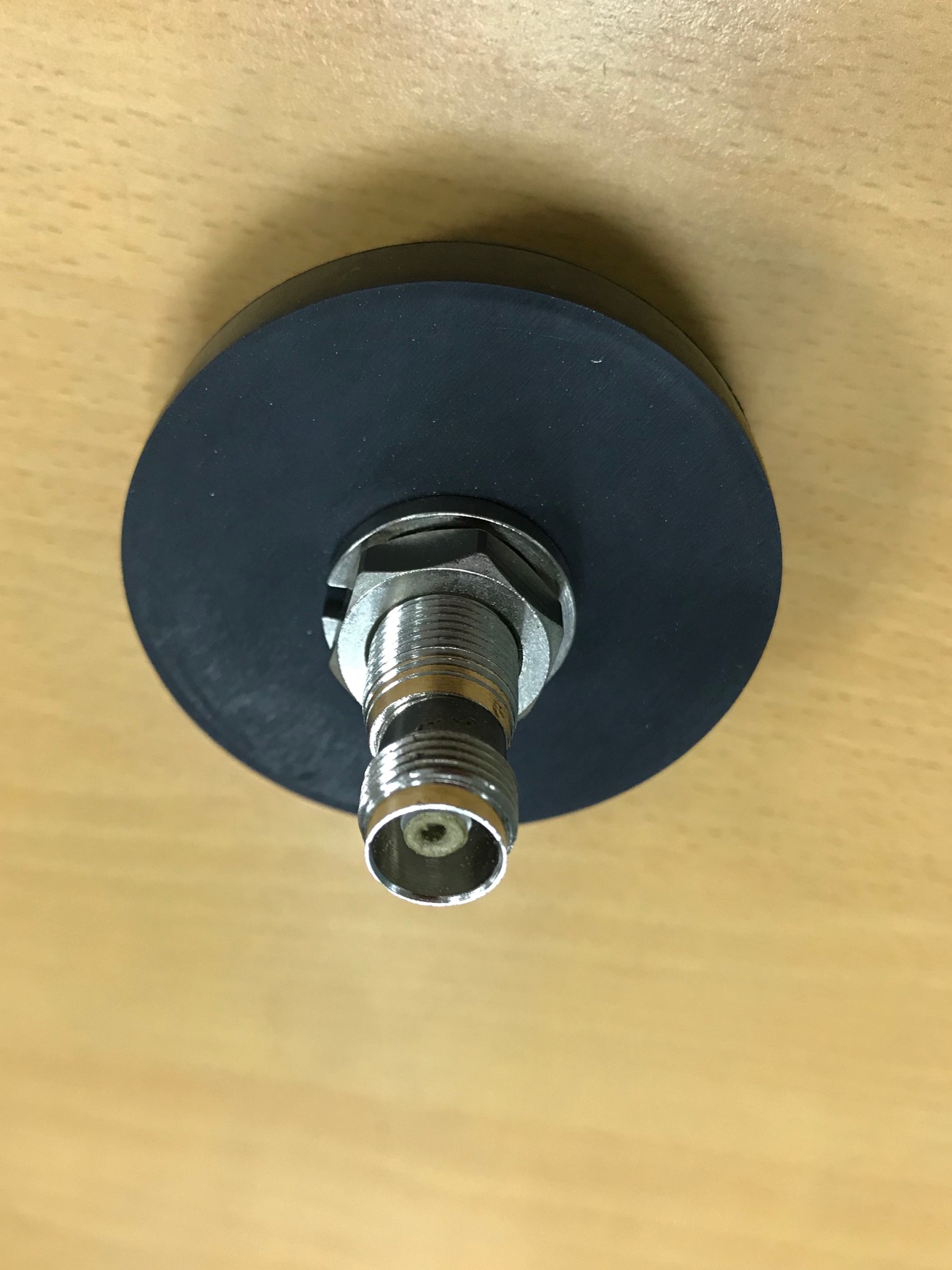
Connector
|
TNC Female
|
|
Operating Temperature Range
|
-30ĪŃC~+75ĪŃC
|
|
Storage Temperature Range
|
-40ĪŃC~+80ĪŃC
|
|
Dimension
|
Dimension See Page.
|
